Welcome, Guest
Username: Password: Remember me
  • Page:
  • 1

TOPIC: Mark78

Mark78 13 years 10 months ago #22537

  • joenawlins
  • joenawlins's Avatar Topic Author
  • Offline
  • Contributing Member
  • Contributing Member
  • Posts: 554
  • Karma: 6
  • Thank you received: 0
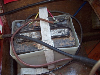
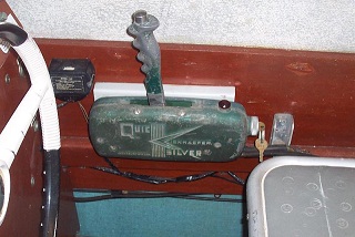
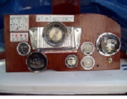
Hey Doc, I have a couple of ques about elec stuff. I'm attaching a couple of pics and wondering if you can help. What does this controller do and can I get a replacement anywhere? Plus I was splicing the 2 small wires coming out of the external harness w/batt hooked up and stupidly I fried those off and thought the boat was going to burn up! I have no power to tach and ampmeter as a result. Thx Joe

Please Log in or Create an account to join the conversation.

Re:Mark78 13 years 10 months ago #22538

  • joenawlins
  • joenawlins's Avatar Topic Author
  • Offline
  • Contributing Member
  • Contributing Member
  • Posts: 554
  • Karma: 6
  • Thank you received: 0
have to re-size brb
Attachments:

Please Log in or Create an account to join the conversation.

Re:Mark78 13 years 10 months ago #22541

  • joenawlins
  • joenawlins's Avatar Topic Author
  • Offline
  • Contributing Member
  • Contributing Member
  • Posts: 554
  • Karma: 6
  • Thank you received: 0
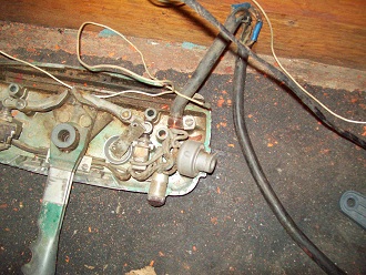
the ones I fried are the taped wires at bott of 2nd pic

Please Log in or Create an account to join the conversation.

Re:Mark78 13 years 10 months ago #22546

Joe,
I don't recognize the black gizmoe from what I can see of it and I can't tell which wires (points of origin and destination + colors) got fried.
Where was the black thing located? (under the dash? on the Merc? or?)
If I was to guess - which I don't like to do when I flat don't know - would be that perhaps the black thing might have something to do with an old school tachometer - but don't trust that guess at all.
:huh:
Thom

Please Log in or Create an account to join the conversation.

Re:Mark78 13 years 10 months ago #22553

  • joenawlins
  • joenawlins's Avatar Topic Author
  • Offline
  • Contributing Member
  • Contributing Member
  • Posts: 554
  • Karma: 6
  • Thank you received: 0
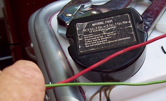
Tried to find some better pics but don't think I do. The box says 12V battery control and is by Airguide. I have an airguide tach. In the new pic the front 2 wires out of box go to ampmeter. The other wires go back to the harness and are the ones I fried the other end of. I"m guessing they come off of the switch in control box. I have a 78A delivered this week with harness and maybe that will help me figure it out???
Attachments:

Please Log in or Create an account to join the conversation.

Re:Mark78 13 years 10 months ago #22554

  • Kerry
  • Offline
  • Gold Boarder
  • Gold Boarder
  • Posts: 675
  • Karma: 51
  • Thank you received: 2
Zoom shows made by Airguide, model 651. Airguide 651B uses a separate transmitter- the box in the pics. www.classicboatwork.com/classicparts/gauges/airguide/airguideinstructions/Airguide%20653%20Instructions%20Tachometers.pdf

Please Log in or Create an account to join the conversation.

Re:Mark78 13 years 10 months ago #22555

  • joenawlins
  • joenawlins's Avatar Topic Author
  • Offline
  • Contributing Member
  • Contributing Member
  • Posts: 554
  • Karma: 6
  • Thank you received: 0
having too much trouble finding and loading pics. I'll try another day.thx,Joe

Please Log in or Create an account to join the conversation.

Re:Mark78 13 years 10 months ago #22556

  • joenawlins
  • joenawlins's Avatar Topic Author
  • Offline
  • Contributing Member
  • Contributing Member
  • Posts: 554
  • Karma: 6
  • Thank you received: 0
Thx Kerry, I tried looking fo something like this months ago when I was trying to fig it out. All the wires on are cloth wrapped. I re-did all of the wiring except for that including getting rid of bus term and putting in fuse block.

Please Log in or Create an account to join the conversation.

Re:Mark78 13 years 10 months ago #22561

  • Kerry
  • Offline
  • Gold Boarder
  • Gold Boarder
  • Posts: 675
  • Karma: 51
  • Thank you received: 2
I just hope you didn't hurt that transformer.

Please Log in or Create an account to join the conversation.

Re:Mark78 13 years 10 months ago #22562

  • joenawlins
  • joenawlins's Avatar Topic Author
  • Offline
  • Contributing Member
  • Contributing Member
  • Posts: 554
  • Karma: 6
  • Thank you received: 0
Nope,fried wires going from batt to harness. Good sight, I have vintage compass NIB w/cracked glass and might try to swap them for something.

Please Log in or Create an account to join the conversation.

Re:Mark78 13 years 10 months ago #22582

  • 63g3
  • Offline
  • Contributing Member
  • Contributing Member
  • Posts: 465
  • Karma: 62
  • Thank you received: 2
Wow, lots of tach questions today. I'll try and help here too.
Where these instruments originally used on your motor?
There is some contradictory info. the module you have appears to work with a 2 cyl or 4 cyl. Typically with the ignition system in your motor you need a tach/module that will read a three cylinder two cycle (as mentioned for the Scott) or a 6 cylinder four stroke.
You can pick off the signal from one of the coils in these senarios for correct RPM. Each coil is operating as a three cylinder two cycle ignition system. So, the same number of pulses per revolution as the 3 cyl Scott. Or similarly each coil fires three times per crank revolution the same as a coil would in a 6 cyl four stoke motor. I look for vintage tachs for 6 cyl 4 strokes when wanting to use a tach on these 6 cyl dual coil set-ups. The correct two cycle tachs and modules are hard to come by.
As far as your AMP meter, is this also stock to the boat? This is a very circituitous way to see if battery is charging. This is more typically done with a voltage reading.
The early Direct Reverse motors ran a switched charging wire up to the control switch and then back to the battery. Your AMP meter needs to be somewhere in this charging wire circuit so the charging current goes through it. A voltage meter is much simpler because you only need to read the voltage at the battery terminals so it is a direct hookup without involving the motor wiring although you could still splice into it. You will find the charging voltage simply increases above static battery voltage with increasing RPM. These are very simple charging circuits. They are also barely adaquate. That's why the bad reputation of the D.R. motors, often battery was too weak to crank and start motor which was problematic around the dock.
Bob Grubb suggests the following: Forget about running the charging wire throught the control, simply put a jumper between the output of the rectifier and the large always hot, +12 volt wire that goes to the starter solenoid. Note: I would also switch from a plate style rectifier to the later block diode style rectifier.
You could wire in your amp meter to this jumper but that would entail running the jumper all the way up to the dash and back, creating a similar problem with long wire runs in the charging circuit. Try and find a period volt meter it's a better way to go.
My two cents,
Randy

Please Log in or Create an account to join the conversation.

  • Page:
  • 1
Time to create page: 0.198 seconds

Donate

Please consider supporting our efforts.

Glassified Ads

1967 23 ft powercat flybridge
( / Boats)

noimage
11-17-2024

Mercury outboard
( / Engines)

noimage
11-03-2024

Classic Mercury Outboard Motors
( / Engines)

Classic Mercury Outboard Motors
10-18-2024

FG Login

FiberGoogle

Who's Online

We have 6058 guests and one member online