|
Welcome,
Guest
|
TOPIC: 1963 Glastron V143 JetFlite Restoration
1963 Glastron V143 JetFlite Restoration 6 years 11 months ago #139533
|
Please Log in or Create an account to join the conversation. |

1963 Glastron V143 JetFlite Restoration 6 years 11 months ago #139537
|
|
Please Log in or Create an account to join the conversation. |

1963 Glastron V143 JetFlite Restoration 6 years 11 months ago #139542
|
Please Log in or Create an account to join the conversation. |
1963 Glastron V143 JetFlite Restoration 6 years 4 months ago #141608
|
Please Log in or Create an account to join the conversation. |

1963 Glastron V143 JetFlite Restoration 6 years 3 months ago #141612
|
|
Please Log in or Create an account to join the conversation. |
1963 Glastron V143 JetFlite Restoration 6 years 3 months ago #141694
|
Please Log in or Create an account to join the conversation. |

1963 Glastron V143 JetFlite Restoration 6 years 2 months ago #141834
|
Please Log in or Create an account to join the conversation. |

1963 Glastron V143 JetFlite Restoration 6 years 2 months ago #141842
|
|
Please Log in or Create an account to join the conversation.
Profile Picture:
E. Carl Kiekhaefer (Mercury Founder) & Joe Poole Sr. @ 1964 Mercury Dealer Meeting |
1963 Glastron V143 JetFlite Restoration 6 years 2 months ago #141845
|
Please Log in or Create an account to join the conversation. |
1963 Glastron V143 JetFlite Restoration 6 years 2 months ago #141848
|
|
Please Log in or Create an account to join the conversation.
Profile Picture:
E. Carl Kiekhaefer (Mercury Founder) & Joe Poole Sr. @ 1964 Mercury Dealer Meeting |
1963 Glastron V143 JetFlite Restoration 6 years 2 months ago #141851
|
Please Log in or Create an account to join the conversation. |
1963 Glastron V143 JetFlite Restoration 6 years 2 months ago #141855
|
|
Please Log in or Create an account to join the conversation.
Profile Picture:
E. Carl Kiekhaefer (Mercury Founder) & Joe Poole Sr. @ 1964 Mercury Dealer Meeting |

1963 Glastron V143 JetFlite Restoration 4 years 4 months ago #145893
|
|
Please Log in or Create an account to join the conversation. |
1963 Glastron V143 JetFlite Restoration 4 years 4 months ago #145903
|
Please Log in or Create an account to join the conversation. |
Donate
Please consider supporting our efforts.
Glassified Ads
1962 Scott - last chance! |

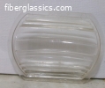
Light Lens 6356-03 Attwood Marine Transom( / Parts / Miscellaneous)

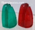
Attwood 6000-09 Green & Red Side Light( / Parts / Miscellaneous)


FG Login

FiberGoogle
Who's Online
We have 6165 guests and 2 members online